Microprocessor
Microprocessor-8085 Architecture
8085 is pronounced as "eighty-eighty-five" microprocessor. It is an 8-bit microprocessor designed by Intel in 1977 using NMOS technology.
It has the following configuration −
- 8-bit data bus
- 16-bit address bus, which can address upto 64KB
- A 16-bit program counter
- A 16-bit stack pointer
- Six 8-bit registers arranged in pairs: BC, DE, HL
- Requires +5V supply to operate at 3.2 MHZ single phase clock
It is used in washing machines, microwave ovens, mobile phones, etc.
8085 Microprocessor – Functional Units
8085 consists of the following functional units −
Accumulator
It is an 8-bit register used to perform arithmetic, logical, I/O & LOAD/STORE operations. It is connected to internal data bus & ALU.
Arithmetic and logic unit
As the name suggests, it performs arithmetic and logical operations like Addition, Subtraction, AND, OR, etc. on 8-bit data.
General purpose register
There are 6 general purpose registers in 8085 processor, i.e. B, C, D, E, H & L. Each register can hold 8-bit data.
These registers can work in pair to hold 16-bit data and their pairing combination is like B-C, D-E & H-L.
Program counter
It is a 16-bit register used to store the memory address location of the next instruction to be executed. Microprocessor increments the program whenever an instruction is being executed, so that the program counter points to the memory address of the next instruction that is going to be executed.
Stack pointer
It is also a 16-bit register works like stack, which is always incremented/decremented by 2 during push & pop operations.
Temporary register
It is an 8-bit register, which holds the temporary data of arithmetic and logical operations.
Flag register
It is an 8-bit register having five 1-bit flip-flops, which holds either 0 or 1 depending upon the result stored in the accumulator.
These are the set of 5 flip-flops −
- Sign (S)
- Zero (Z)
- Auxiliary Carry (AC)
- Parity (P)
- Carry (C)
Its bit position is shown in the following table −
| D7 | D6 | D5 | D4 | D3 | D2 | D1 | D0 |
|---|---|---|---|---|---|---|---|
| S | Z | AC | P | CY | |||
| #### Instruction register and decoder |
It is an 8-bit register. When an instruction is fetched from memory then it is stored in the Instruction register. Instruction decoder decodes the information present in the Instruction register.
Timing and control unit
It provides timing and control signal to the microprocessor to perform operations. Following are the timing and control signals, which control external and internal circuits −
- Control Signals: READY, RD’, WR’, ALE
- Status Signals: S0, S1, IO/M’
- DMA Signals: HOLD, HLDA
- RESET Signals: RESET IN, RESET OUT
Interrupt control
As the name suggests it controls the interrupts during a process. When a microprocessor is executing a main program and whenever an interrupt occurs, the microprocessor shifts the control from the main program to process the incoming request. After the request is completed, the control goes back to the main program.
There are 5 interrupt signals in 8085 microprocessor: INTR, RST 7.5, RST 6.5, RST 5.5, TRAP.
Serial Input/output control
It controls the serial data communication by using these two instructions: SID (Serial input data) and SOD (Serial output data).
Address buffer and address-data buffer
The content stored in the stack pointer and program counter is loaded into the address buffer and address-data buffer to communicate with the CPU. The memory and I/O chips are connected to these buses; the CPU can exchange the desired data with the memory and I/O chips.
Address bus and data bus
Data bus carries the data to be stored. It is bidirectional, whereas address bus carries the location to where it should be stored and it is unidirectional. It is used to transfer the data & Address I/O devices.
Microprocessor - 8086 Overview
8086 Microprocessor is an enhanced version of 8085Microprocessor that was designed by Intel in 1976. It is a 16-bit Microprocessor having 20 address lines and16 data lines that provides up to 1MB storage. It consists of powerful instruction set, which provides operations like multiplication and division easily.
It supports two modes of operation, i.e. Maximum mode and Minimum mode. Maximum mode is suitable for system having multiple processors and Minimum mode is suitable for system having a single processor.
Features of 8086
The most prominent features of a 8086 microprocessor are as follows −
-
It has an instruction queue, which is capable of storing six instruction bytes from the memory resulting in faster processing.
-
It was the first 16-bit processor having 16-bit ALU, 16-bit registers, internal data bus, and 16-bit external data bus resulting in faster processing.
-
It is available in 3 versions based on the frequency of operation −
-
8086 → 5MHz
-
8086-2 → 8MHz
-
(c)8086-1 → 10 MHz
-
-
It uses two stages of pipelining, i.e. Fetch Stage and Execute Stage, which improves performance.
-
Fetch stage can prefetch up to 6 bytes of instructions and stores them in the queue.
-
Execute stage executes these instructions.
-
It has 256 vectored interrupts.
-
It consists of 29,000 transistors.
Comparison between 8085 & 8086 Microprocessor
-
Size − 8085 is 8-bit microprocessor, whereas 8086 is 16-bit microprocessor.
-
Address Bus − 8085 has 16-bit address bus while 8086 has 20-bit address bus.
-
Memory − 8085 can access up to 64Kb, whereas 8086 can access up to 1 Mb of memory.
-
Instruction − 8085 doesn’t have an instruction queue, whereas 8086 has an instruction queue.
-
Pipelining − 8085 doesn’t support a pipelined architecture while 8086 supports a pipelined architecture.
-
I/O − 8085 can address 2^8 = 256 I/O's, whereas 8086 can access 2^16 = 65,536 I/O's.
-
Cost − The cost of 8085 is low whereas that of 8086 is high.
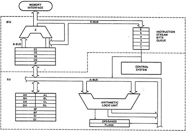
Architecture of 8086
The following diagram depicts the architecture of a 8086 Microprocessor −
8085 Programming Model
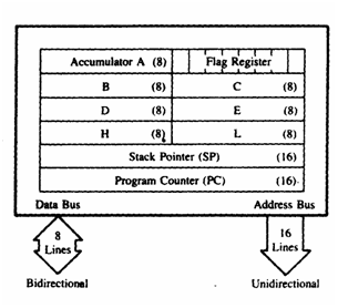
A programming model 8085
1. Registers
- The 8085 has six general purpose registers to store 8 bit data; these are identifies as B, C, D, E, H, L.
- They can be combined as register pairs - BC, DE and HL to perform some 16-bit operations.
- The programmer can use these registers to store or copy data into the registers by using data copy instructions.
2. Accumulator
- The accumulator is an 8-bit register that is a part of arithmetic/logic unit(ALU).
- This register is used to store 8-bit data and to perform arithmetic and logical operations.
- The result of an operation is stored in the accumulator.
- The accumulator is also identified as register A.
3. Flags

Bit positions of various flags in the flag register of 8085
-
8085 has five flag registers:-
-
Sign Flag (S): Sets or Resets based on the result stored in the accumulator.
If the result stored is positive, the flag resets else if the result stored is negative the flag is set.
- Zero Flag (Z): Sets or Resets based on the result stored in the accumulator.
If the result stored is zero the flag is set else it is reset.
-
Auxiliary Carry Flag(AC) : This flag is set if there is a carry from low nibble(lowest 4 bits) to high nibble(upper 4 bits) or a borrow from high nibble to low nibble, in the low order 8-bit portion of an addition or subtraction operation.
-
Parity Flag (P): This flag is set if there is even parity else it resets.
-
Carry Flag (CY): This flag is set if there is a carry bit else it resets.
4. Program Counter (PC)
- This 16-bit register deals with sequencing the execution of instructions this register is a memory pointer.
- Memory locations have 16 bit addresses and that is why this is a 16 bit register.
- The function of the PC is to point to the memory address from which the next byte is to be fetched.
- When a byte(machine code) is being fetched, the program counter is incremented by one to point to the next memory location.
5. Stack Pointer (SP)
- The stack pointer is also a 16-bit register used as a memory pointer.
- It points to a memory location in R/W memory called stack.
- The beggining of the stack is defined by loading 16-bit address in the stack pointer.
A programming model of 8086
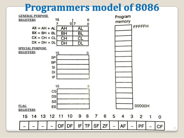
The programming model for a microprocessor shows the various internal registers that are accessible to the programmer.
The Following Figure is a model for the 8086. In general, each register has a special function.
In the programming model there are
-
4 General Purpose registers( Data Registers)
-
4 Segment registers
-
2 Pointer registers
-
2 Index registers
-
1 Instruction Pointer register
-
1 Flag register
General purpose registers:
AX Register (Accumulator): This is accumulator register. It gets used in arithmetic, logic and data transfer instructions. In manipulation and division, one of the numbers involved must be in AX or AL.
BX Register (Base Register): This is base register. BX register is an address register. It usually contain a data pointer used for based, based indexed or register indirect addressing.
CX Register (Counter register): This is Count register. This serves as a loop counter. Program loop constructions are facilitated by it. Count register can also be used as a counter in string manipulation and shift/rotate instruction.
DX Register (Data Register): This is data register. Data register can be used as a port number in I/O operations. It is also used in multiplication and division.
Segement Registers:
There are four segment registers in Intel 8086:
-
Code Segment Register (CS),
-
Data Segment Register (DS),
-
Stack Segment Register (SS),
-
Extra Segment Register (ES).
A segment register points to the starting address of a memory segment. Maximum capacity of a segment may be up to 64 KB.
Code segment Register(CS):- It is a 16-bit register containing the starting address of 64 KB segment. The processor uses CS segment for all accesses to instructions referenced by instruction pointer (IP) register.
Stack segment Register (SS):- It is a 16-bit register containing address of 64KB segment with program stack. By default, the processor assumes that all data referenced by the stack pointer (SP) and base pointer (BP) registers is located in the stack segment. SS register can be changed directly using POP instruction.
Data segment Register (DS):- It is a 16-bit register containing address of 64KB segment with program data. By default, the processor assumes that all data referenced by general registers (AX, BX, CX, DX) and index register (SI, DI) is located in the data segment.
Extra segment Register (ES):- It is a 16-bit register containing address of 64KB segment, usually with program data. By default, the processor assumes that the DI register references the ES segment in string manipulation instructions. It is possible to change default segments used by general and index registers by prefixing instructions with a CS, SS,DS or ES prefix.
Pointer Registers:
SP Register (Stack Pointer): This is stack pointer register pointing to program stack. It is used in conjunction with SS for accessing the stack segment.
BP Register (Base Pointer): This is base pointer register pointing to data in stack segment. Unlike SP, we can use BP to access data in the other segments.
Index Registers:
SI Register (Source Index): This is used to point to memory locations in the data segment addressed by DS. By incrementing the contents of SI one can easily access consecutive memory locations.
DI Register (Destination Index): This register performs the same function as SI. There is a class of instructions called string operations, that use DI to access the memory locations addressed by ES.
Instruction Pointer: The Instruction Pointer (IP) points to the address of the next instruction to be executed. Its content is automatically incremented when the execution of a program proceeds further. The contents of the IP and Code Segment Register are used to compute the memory address of the instruction code to be fetched. This is done during the Fetch Cycle.
Flag Register: Status Flags determines the current state of the accumulator. They are modified automatically by CPU after mathematical operations. This allows to determine the type of the result. 8086 has 16-bit status register. It is also called Flag Register or Program Status Word (PSW). There are nine status flags and seven bit positions remain unused.
8086 has 16 flag registers among which 9 are active. The purpose of the FLAGS register is to indicate the status of the processor. It does this by setting the individual bits called flags. There are two kinds of FLAGS;
Status FLAGS and Control FLAGS. Status FLAGS reflect the result of an operation executed by the processor. The control FLAGS enable or disable certain operations of the processor.
Reference
https://www.tutorialspoint.com/microprocessor/microprocessor_8085_architecture.htm https://www.tutorialspoint.com/microprocessor/microprocessor_8086_overview.htm https://csenotesforyou.blogspot.com/2016/06/8085-programming-model.html