Optimality Principle in Network Topology
Classification of Routing Algorithms
Routing is the process of establishing the routes that data packets must follow to reach the destination. In this process, a routing table is created which contains information regarding routes that data packets follow. Various routing algorithms are used for the purpose of deciding which route an incoming data packet needs to be transmitted on to reach the destination efficiently.
Classification of Routing Algorithms
The routing algorithms can be classified as follows:
- Adaptive Algorithms
- Non-Adaptive Algorithms
- Hybrid Algorithms
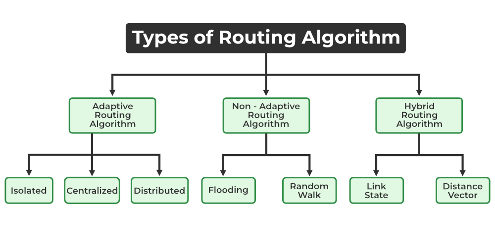
Types of Routing Algorithm
1. Adaptive Algorithms
These are the algorithms that change their routing decisions whenever network topology or traffic load changes. The changes in routing decisions are reflected in the topology as well as the traffic of the network. Also known as dynamic routing, these make use of dynamic information such as current topology, load, delay, etc. to select routes. Optimization parameters are distance, number of hops, and estimated transit time.
Further, these are classified as follows:
- Isolated: In this method each, node makes its routing decisions using the information it has without seeking information from other nodes. The sending nodes don’t have information about the status of a particular link. The disadvantage is that packets may be sent through a congested network which may result in delay. Examples: Hot potato routing, and backward learning.
- Centralized: In this method, a centralized node has entire information about the network and makes all the routing decisions. The advantage of this is only one node is required to keep the information of the entire network and the disadvantage is that if the central node goes down the entire network is done. The link state algorithm is referred to as a centralized algorithm since it is aware of the cost of each link in the network.
- Distributed: In this method, the node receives information from its neighbors and then takes the decision about routing the packets. A disadvantage is that the packet may be delayed if there is a change in between intervals in which it receives information and sends packets. It is also known as a decentralized algorithm as it computes the least-cost path between source and destination.
2. Non-Adaptive Algorithms
These are the algorithms that do not change their routing decisions once they have been selected. This is also known as static routing as a route to be taken is computed in advance and downloaded to routers when a router is booted.
Further, these are classified as follows:
- Flooding: This adapts the technique in which every incoming packet is sent on every outgoing line except from which it arrived. One problem with this is that packets may go in a loop and as a result of which a node may receive duplicate packets. These problems can be overcome with the help of sequence numbers, hop count, and spanning trees.
- Random walk: In this method, packets are sent host by host or node by node to one of its neighbors randomly. This is a highly robust method that is usually implemented by sending packets onto the link which is least queued.
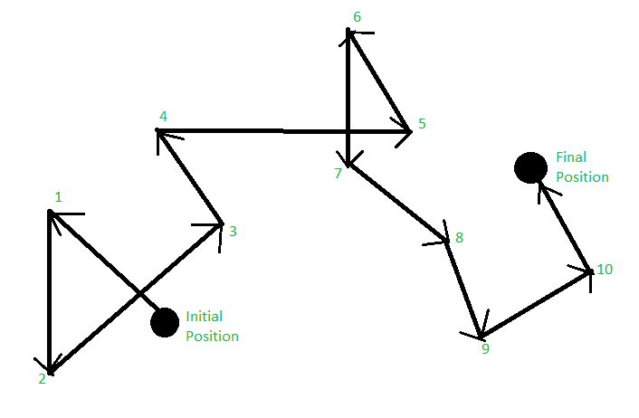
Random Walk
3. Hybrid Algorithms
As the name suggests, these algorithms are a combination of both adaptive and non-adaptive algorithms. In this approach, the network is divided into several regions, and each region uses a different algorithm.
Further, these are classified as follows:
- Link-state: In this method, each router creates a detailed and complete map of the network which is then shared with all other routers. This allows for more accurate and efficient routing decisions to be made.
- Distance vector: In this method, each router maintains a table that contains information about the distance and direction to every other node in the network. This table is then shared with other routers in the network. The disadvantage of this method is that it may lead to routing loops.
Introduction :
A general statement is made about optimal routes without regard to network topology or traffic. This statement is known as the optimality principle( Bellman,1975).
Statement of the optimality principle :
It states that if the router J is on the optimal path from router I to router K, then the optimal path from J to K also falls along the same route. Call the route from I to J r1 and the rest of the route r2. it could be concatenated with r1 to improve the route from I to K, contradicting our statement that r1r2 is optimal only if a route better than r2 existed from J to K.
Sink Tree for routers :
We can see that the set of optimal routes from all sources to a given destination from a tree rooted at the destination as a directed consequence of the optimality principle. This tree is called a sink tree and is illustrated in fig(1).
Description of figure :
In the given figure the distance metric is the number of hops. Therefore, the goal of all routing algorithms is to discover and use the sink trees for all routers.

(a) A network

(b) A sink tree for router B
The sink tree is not unique also other trees with the same path lengths may exist. If we allow all of the possible paths to be chosen, the tree becomes a more general structure called a DAG (Directed Acyclic Graph). DAGs have no loops. We will use sink trees as a convenient shorthand for both cases. we will take technical assumption for both cases that the paths do not interfere with each other so, for example, a traffic jam on one path will not cause another path to divert.
Conclusion :
The sink tree does not contain any loops, so each packet will be delivered within a finite and bounded number of hops. In practice, life is not quite easy. Links and routers can go on and come back up during operation, so different routers may have different ideas about the current topology. Also, we have found the issue of whether each router has to individually acquire the information on which to base its sink tree computation or whether this information is collected by some other means. Sink tree and the optimality principle provide a benchmark against which other routing algorithms can be measured.
Shortest Path Routing in Computer Network?
In this algorithm, to select a route, the algorithm discovers the shortest path between two nodes. It can use multiple hops, the geographical area in kilometres or labelling of arcs for measuring path length.
The labelling of arcs can be done with mean queuing, transmission delay for a standard test packet on an hourly basis, or computed as a function of bandwidth, average distance traffic, communication cost, mean queue length, measured delay or some other factors.
In shortest path routing, the topology communication network is defined using a directed weighted graph. The nodes in the graph define switching components and the directed arcs in the graph define communication connection between switching components. Each arc has a weight that defines the cost of sharing a packet between two nodes in a specific direction.
This cost is usually a positive value that can denote such factors as delay, throughput, error rate, financial costs, etc. A path between two nodes can go through various intermediary nodes and arcs. The goal of shortest path routing is to find a path between two nodes that has the lowest total cost, where the total cost of a path is the sum of arc costs in that path.
For example, Dijikstra uses the nodes labelling with its distance from the source node along the better-known route. Initially, all nodes are labelled with infinity, and as the algorithm proceeds, the label may change. The labelling graph is displayed in the figure.
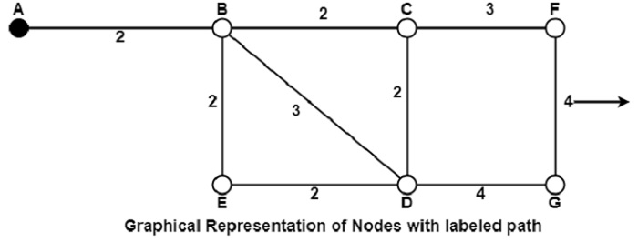
It can be done in various passes as follows, with A as the source.
-
Pass 1. B (2, A), C(∞,−), F(∞,−), e(∞,−), d(∞,−), G 60
-
Pass 2. B (2, A), C(4, B), D(5, B), E(4, B), F(∞,−),G(∞,−)
-
Pass 3. B(2, A), C(4, B), D(5, B), E(4, B), F(7, C), G(9, D)
We can see that there can be two paths between A and G. One follows through ABCFG and the other through ABDG. The first one has a path length of 11, while the second one has 9. Hence, the second one, as G (9, D), is selected. Similarly, Node D has also three paths from A as ABD, ABCD and ABED. The first one has a path length of 5 rest two have 6. So, the first one is selected.
All nodes are searched in various passes, and finally, the routes with the shortest path lengths are made permanent, and the nodes of the path are used as a working node for the next round.
Flooding in Computer Network
Flooding is a non-adaptive routing technique following this simple method: when a data packet arrives at a router, it is sent to all the outgoing links except the one it has arrived on.
For example, let us consider the network in the figure, having six routers that are connected through transmission lines.
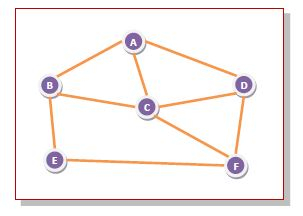
Using flooding technique −
-
An incoming packet to A, will be sent to B, C and D.
-
B will send the packet to C and E.
-
C will send the packet to B, D and F.
-
D will send the packet to C and F.
-
E will send the packet to F.
-
F will send the packet to C and E.
Types of Flooding
Flooding may be of three types −
-
Uncontrolled flooding − Here, each router unconditionally transmits the incoming data packets to all its neighbours.
-
Controlled flooding − They use some methods to control the transmission of packets to the neighbouring nodes. The two popular algorithms for controlled flooding are Sequence Number Controlled Flooding (SNCF) and Reverse Path Forwarding (RPF).
-
Selective flooding − Here, the routers don't transmit the incoming packets only along those paths which are heading towards approximately in the right direction, instead of every available paths.
Advantages of Flooding
-
It is very simple to setup and implement, since a router may know only its neighbours.
-
It is extremely robust. Even in case of malfunctioning of a large number routers, the packets find a way to reach the destination.
-
All nodes which are directly or indirectly connected are visited. So, there are no chances for any node to be left out. This is a main criteria in case of broadcast messages.
-
The shortest path is always chosen by flooding.
Limitations of Flooding
-
Flooding tends to create an infinite number of duplicate data packets, unless some measures are adopted to damp packet generation.
-
It is wasteful if a single destination needs the packet, since it delivers the data packet to all nodes irrespective of the destination.
-
The network may be clogged with unwanted and duplicate data packets. This may hamper delivery of other data packets.
Distance Vector Routing (DVR) Protocol
A distance-vector routing (DVR) protocol requires that a router inform its neighbors of topology changes periodically. Historically known as the old ARPANET routing algorithm (or known as Bellman-Ford algorithm).
Bellman Ford Basics – Each router maintains a Distance Vector table containing the distance between itself and ALL possible destination nodes. Distances,based on a chosen metric, are computed using information from the neighbors’ distance vectors.
Information kept by DV router -
- Each router has an ID
- Associated with each link connected to a router, there is a link cost (static or dynamic).
- Intermediate hops
Distance Vector Table Initialization -
- Distance to itself = 0
- Distance to ALL other routers = infinity number.
Distance Vector Algorithm –
- A router transmits its distance vector to each of its neighbors in a routing packet.
- Each router receives and saves the most recently received distance vector from each of its neighbors.
- A router recalculates its distance vector when:
- It receives a distance vector from a neighbor containing different information than before.
- It discovers that a link to a neighbor has gone down.
The DV calculation is based on minimizing the cost to each destination
Dx(y) = Estimate of least cost from x to y C(x,v) = Node x knows cost to each neighbor v Dx = [Dx(y): y ? N ] = Node x maintains distance vector Node x also maintains its neighbors' distance vectors – For each neighbor v, x maintains Dv = [Dv(y): y ? N ]
Note –
- From time-to-time, each node sends its own distance vector estimate to neighbors.
-
When a node x receives new DV estimate from any neighbor v, it saves v’s distance vector and it updates its own DV using B-F equation:
Dx(y) = min { C(x,v) + Dv(y), Dx(y) } for each node y ? N
Example – Consider 3-routers X, Y and Z as shown in figure. Each router have their routing table. Every routing table will contain distance to the destination nodes.

Consider router X , X will share it routing table to neighbors and neighbors will share it routing table to it to X and distance from node X to destination will be calculated using bellmen- ford equation.
Dx(y) = min { C(x,v) + Dv(y)} for each node y ? N
As we can see that distance will be less going from X to Z when Y is intermediate node(hop) so it will be update in routing table X.

Similarly for Z also –

Finally the routing table for all –

Advantages of Distance Vector routing –
- It is simpler to configure and maintain than link state routing.
Disadvantages of Distance Vector routing –
- It is slower to converge than link state.
- It is at risk from the count-to-infinity problem.
- It creates more traffic than link state since a hop count change must be propagated to all routers and processed on each router. Hop count updates take place on a periodic basis, even if there are no changes in the network topology, so bandwidth-wasting broadcasts still occur.
- For larger networks, distance vector routing results in larger routing tables than link state since each router must know about all other routers. This can also lead to congestion on WAN links.
Link State Routing
Link state routing is a technique in which each router shares the knowledge of its neighborhood with every other router in the internetwork.
The three keys to understand the Link State Routing algorithm:
- Knowledge about the neighborhood: Instead of sending its routing table, a router sends the information about its neighborhood only. A router broadcast its identities and cost of the directly attached links to other routers.
- Flooding: Each router sends the information to every other router on the internetwork except its neighbors. This process is known as Flooding. Every router that receives the packet sends the copies to all its neighbors. Finally, each and every router receives a copy of the same information.
- Information sharing: A router sends the information to every other router only when the change occurs in the information.
Link State Routing has two phases:
Reliable Flooding
- Initial state: Each node knows the cost of its neighbors.
- Final state: Each node knows the entire graph.
Route Calculation
Each node uses Dijkstra's algorithm on the graph to calculate the optimal routes to all nodes.
- The Link state routing algorithm is also known as Dijkstra's algorithm which is used to find the shortest path from one node to every other node in the network.
- The Dijkstra's algorithm is an iterative, and it has the property that after kth iteration of the algorithm, the least cost paths are well known for k destination nodes.
Let's describe some notations:
- c( i , j): Link cost from node i to node j. If i and j nodes are not directly linked, then c(i , j) = ∞.
- D(v): It defines the cost of the path from source code to destination v that has the least cost currently.
- P(v): It defines the previous node (neighbor of v) along with current least cost path from source to v.
- N: It is the total number of nodes available in the network.
Algorithm
Initialization N = {A} // A is a root node. for all nodes v if v adjacent to A then D(v) = c(A,v) else D(v) = infinity loop find w not in N such that D(w) is a minimum. Add w to N Update D(v) for all v adjacent to w and not in N: D(v) = min(D(v) , D(w) + c(w,v)) Until all nodes in N
In the above algorithm, an initialization step is followed by the loop. The number of times the loop is executed is equal to the total number of nodes available in the network.
Let's understand through an example:
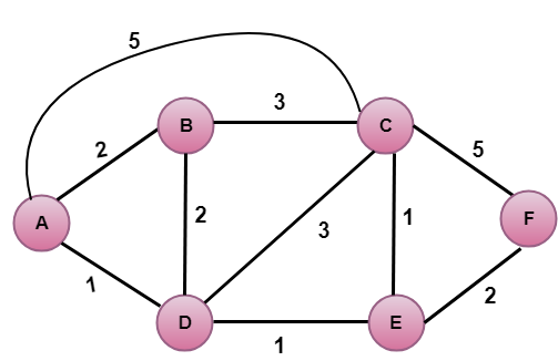
In the above figure, source vertex is A.
Step 1:
The first step is an initialization step. The currently known least cost path from A to its directly attached neighbors, B, C, D are 2,5,1 respectively. The cost from A to B is set to 2, from A to D is set to 1 and from A to C is set to 5. The cost from A to E and F are set to infinity as they are not directly linked to A.
| Step | N | D(B),P(B) | D(C),P(C) | D(D),P(D) | D(E),P(E) | D(F),P(F) |
|---|---|---|---|---|---|---|
| 1 | A | 2,A | 5,A | 1,A | ∞ | ∞ |
Step 2:
In the above table, we observe that vertex D contains the least cost path in step 1. Therefore, it is added in N. Now, we need to determine a least-cost path through D vertex.
a) Calculating shortest path from A to B
- v = B, w = D
- D(B) = min( D(B) , D(D) + c(D,B) )
- = min( 2, 1+2)>
- = min( 2, 3)
- The minimum value is 2. Therefore, the currently shortest path from A to B is 2.
b) Calculating shortest path from A to C
- v = C, w = D
- D(B) = min( D(C) , D(D) + c(D,C) )
- = min( 5, 1+3)
- = min( 5, 4)
- The minimum value is 4. Therefore, the currently shortest path from A to C is 4.
c) Calculating shortest path from A to E
- v = E, w = D
- D(B) = min( D(E) , D(D) + c(D,E) )
- = min( ∞, 1+1)
- = min(∞, 2)
- The minimum value is 2. Therefore, the currently shortest path from A to E is 2.
Note: The vertex D has no direct link to vertex E. Therefore, the value of D(F) is infinity.
| Step | N | D(B),P(B) | D(C),P(C) | D(D),P(D) | D(E),P(E) | D(F),P(F) |
|---|---|---|---|---|---|---|
| 1 | A | 2,A | 5,A | 1,A | ∞ | ∞ |
| 2 | AD | 2,A | 4,D | 2,D | ∞ |
Step 3:
In the above table, we observe that both E and B have the least cost path in step 2. Let's consider the E vertex. Now, we determine the least cost path of remaining vertices through E.
a) Calculating the shortest path from A to B.
- v = B, w = E
- D(B) = min( D(B) , D(E) + c(E,B) )
- = min( 2 , 2+ ∞ )
- = min( 2, ∞)
- The minimum value is 2. Therefore, the currently shortest path from A to B is 2.
b) Calculating the shortest path from A to C.
- v = C, w = E
- D(B) = min( D(C) , D(E) + c(E,C) )
- = min( 4 , 2+1 )
- = min( 4,3)
- The minimum value is 3. Therefore, the currently shortest path from A to C is 3.
c) Calculating the shortest path from A to F.
- v = F, w = E
- D(B) = min( D(F) , D(E) + c(E,F) )
- = min( ∞ , 2+2 )
- = min(∞ ,4)
- The minimum value is 4. Therefore, the currently shortest path from A to F is 4.
| Step | N | D(B),P(B) | D(C),P(C) | D(D),P(D) | D(E),P(E) | D(F),P(F) |
|---|---|---|---|---|---|---|
| 1 | A | 2,A | 5,A | 1,A | ∞ | ∞ |
| 2 | AD | 2,A | 4,D | 2,D | ∞ | |
| 3 | ADE | 2,A | 3,E | 4,E |
Step 4:
In the above table, we observe that B vertex has the least cost path in step 3. Therefore, it is added in N. Now, we determine the least cost path of remaining vertices through B.
a) Calculating the shortest path from A to C.
- v = C, w = B
- D(B) = min( D(C) , D(B) + c(B,C) )
- = min( 3 , 2+3 )
- = min( 3,5)
- The minimum value is 3. Therefore, the currently shortest path from A to C is 3.
b) Calculating the shortest path from A to F.
- v = F, w = B
- D(B) = min( D(F) , D(B) + c(B,F) )
- = min( 4, ∞)
- = min(4, ∞)
- The minimum value is 4. Therefore, the currently shortest path from A to F is 4.
| Step | N | D(B),P(B) | D(C),P(C) | D(D),P(D) | D(E),P(E) | D(F),P(F) |
|---|---|---|---|---|---|---|
| 1 | A | 2,A | 5,A | 1,A | ∞ | ∞ |
| 2 | AD | 2,A | 4,D | 2,D | ∞ | |
| 3 | ADE | 2,A | 3,E | 4,E | ||
| 4 | ADEB | 3,E | 4,E |
Step 5:
In the above table, we observe that C vertex has the least cost path in step 4. Therefore, it is added in N. Now, we determine the least cost path of remaining vertices through C.
a) Calculating the shortest path from A to F.
- v = F, w = C
- D(B) = min( D(F) , D(C) + c(C,F) )
- = min( 4, 3+5)
- = min(4,8)
- The minimum value is 4. Therefore, the currently shortest path from A to F is 4.
| Step | N | D(B),P(B) | D(C),P(C) | D(D),P(D) | D(E),P(E) | D(F),P(F) |
|---|---|---|---|---|---|---|
| 1 | A | 2,A | 5,A | 1,A | ∞ | ∞ |
| 2 | AD | 2,A | 4,D | 2,D | ∞ | |
| 3 | ADE | 2,A | 3,E | 4,E | ||
| 4 | ADEB | 3,E | 4,E | |||
| 5 | ADEBC | 4,E |
Final table:
| Step | N | D(B),P(B) | D(C),P(C) | D(D),P(D) | D(E),P(E) | D(F),P(F) |
|---|---|---|---|---|---|---|
| 1 | A | 2,A | 5,A | 1,A | ∞ | ∞ |
| 2 | AD | 2,A | 4,D | 2,D | ∞ | |
| 3 | ADE | 2,A | 3,E | 4,E | ||
| 4 | ADEB | 3,E | 4,E | |||
| 5 | ADEBC | 4,E | ||||
| 6 | ADEBCF |
Disadvantage:
Heavy traffic is created in Line state routing due to Flooding. Flooding can cause an infinite looping, this problem can be solved by using Time-to-leave field
Hierarchical Routing Protocol:
Hierarchical Routing is the method of routing in networks that is based on hierarchical addressing. Most transmission control protocol, Internet protocol (TCPIP). Routing is based on two level of hierarchical routing in which IP address is divided into a network, person and a host person. Gateways use only the network a person tell an IP data until gateways delivered it directly.
It addresses the growth of routing tables. Routers are further divided into regions and they know the route of their own regions only. It works like a telephone routing.
Example –
City, State, Country, Continent.
Network Layer Services- Packetizing, Routing and Forwarding
The network Layer is the third layer in the OSI model of computer networks. Its main function is to transfer network packets from the source to the destination. It is involved both the source host and the destination host. At the source, it accepts a packet from the transport layer, encapsulates it in a datagram, and then delivers the packet to the data link layer so that it can further be sent to the receiver. At the destination, the datagram is decapsulated, and the packet is extracted and delivered to the corresponding transport layer.
Features of Network Layer
- The main responsibility of the Network layer is to carry the data packets from the source to the destination without changing or using them.
- If the packets are too large for delivery, they are fragmented i.e., broken down into smaller packets.
- It decides the route to be taken by the packets to travel from the source to the destination among the multiple routes available in a network (also called routing).
- The source and destination addresses are added to the data packets inside the network layer.
Services Offered by Network Layer
The services which are offered by the network layer protocol are as follows:
- Packetizing
- Routing
- Forwarding
1. Packetizing
The process of encapsulating the data received from the upper layers of the network (also called payload) in a network layer packet at the source and decapsulating the payload from the network layer packet at the destination is known as packetizing.
The source host adds a header that contains the source and destination address and some other relevant information required by the network layer protocol to the payload received from the upper layer protocol and delivers the packet to the data link layer.
The destination host receives the network layer packet from its data link layer, decapsulates the packet, and delivers the payload to the corresponding upper layer protocol. The routers in the path are not allowed to change either the source or the destination address. The routers in the path are not allowed to decapsulate the packets they receive unless they need to be fragmented.
-768.png)
Packetizing
2. Routing
Routing is the process of moving data from one device to another device. These are two other services offered by the network layer. In a network, there are a number of routes available from the source to the destination. The network layer specifies some strategies which find out the best possible route. This process is referred to as routing. There are a number of routing protocols that are used in this process and they should be run to help the routers coordinate with each other and help in establishing communication throughout the network.

Routing
3. Forwarding
Forwarding is simply defined as the action applied by each router when a packet arrives at one of its interfaces. When a router receives a packet from one of its attached networks, it needs to forward the packet to another attached network (unicast routing) or to some attached networks (in the case of multicast routing). Routers are used on the network for forwarding a packet from the local network to the remote network. So, the process of routing involves packet forwarding from an entry interface out to an exit interface.

Forwarding
Internet Protocol
Here, IP stands for internet protocol. It is a protocol defined in the TCP/IP model used for sending the packets from source to destination. The main task of IP is to deliver the packets from source to the destination based on the IP addresses available in the packet headers. IP defines the packet structure that hides the data which is to be delivered as well as the addressing method that labels the datagram with a source and destination information.
An IP protocol provides the connectionless service, which is accompanied by two transport protocols, i.e., TCP/IP and UDP/IP, so internet protocol is also known as TCP/IP or UDP/IP.
The first version of IP (Internet Protocol) was IPv4. After IPv4, IPv6 came into the market, which has been increasingly used on the public internet since 2006.
History of Internet Protocol
The development of the protocol gets started in 1974 by Bob Kahn and Vint Cerf. It is used in conjunction with the Transmission Control Protocol (TCP), so they together named the TCP/IP.
The first major version of the internet protocol was IPv4, which was version 4. This protocol was officially declared in RFC 791 by the Internet Engineering Task Force (IETF) in 1981.
After IPv4, the second major version of the internet protocol was IPv6, which was version 6. It was officially declared by the IETF in 1998. The main reason behind the development of IPv6 was to replace IPv4. There is a big difference between IPv4 and IPv6 is that IPv4 uses 32 bits for addressing, while IPv6 uses 128 bits for addressing.
Function
The main function of the internet protocol is to provide addressing to the hosts, encapsulating the data into a packet structure, and routing the data from source to the destination across one or more IP networks. In order to achieve these functionalities, internet protocol provides two major things which are given below.
An internet protocol defines two things:
- Format of IP packet
- IP Addressing system
IP packet
Before an IP packet is sent over the network, two major components are added in an IP packet, i.e., header and a payload.
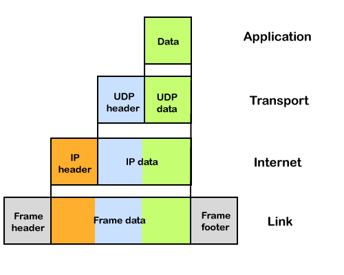
An IP header contains lots of information about the IP packet which includes:
IPv4
IP stands for Internet Protocol and v4 stands for Version Four (IPv4). IPv4 was the primary version brought into action for production within the ARPANET in 1983.
IP version four addresses are 32-bit integers which will be expressed in decimal notation.
Example- 192.0.2.126 could be an IPv4 address.
Parts of IPv4
- Network part:
The network part indicates the distinctive variety that’s appointed to the network. The network part conjointly identifies the category of the network that’s assigned. - Host Part:
The host part uniquely identifies the machine on your network. This part of the IPv4 address is assigned to every host.
For each host on the network, the network part is the same, however, the host half must vary. - Subnet number:
This is the nonobligatory part of IPv4. Local networks that have massive numbers of hosts are divided into subnets and subnet numbers are appointed to that.
Characteristics of IPv4
- IPv4 could be a 32-Bit IP Address.
- IPv4 could be a numeric address, and its bits are separated by a dot.
- The number of header fields is twelve and the length of the header field is twenty.
- It has Unicast, broadcast, and multicast style of addresses.
- IPv4 supports VLSM (Virtual Length Subnet Mask).
- IPv4 uses the Post Address Resolution Protocol to map to the MAC address.
- RIP may be a routing protocol supported by the routed daemon.
- Networks ought to be designed either manually or with DHCP.
- Packet fragmentation permits from routers and causing host.
Advantages of IPv4
- IPv4 security permits encryption to keep up privacy and security.
- IPV4 network allocation is significant and presently has quite 85000 practical routers.
- It becomes easy to attach multiple devices across an outsized network while not NAT.
- This is a model of communication so provides quality service also as economical knowledge transfer.
- IPV4 addresses are redefined and permit flawless encoding.
- Routing is a lot of scalable and economical as a result of addressing is collective more effectively.
- Data communication across the network becomes a lot of specific in multicast organizations.
- Limits net growth for existing users and hinders the use of the net for brand new users.
- Internet Routing is inefficient in IPv4.
- IPv4 has high System Management prices and it’s labor-intensive, complex, slow & frequent to errors.
- Security features are nonobligatory.
- Difficult to feature support for future desires as a result of adding it on is extremely high overhead since it hinders the flexibility to attach everything over IP.
The Limitations of IPv4 Addressing Structure
IPv4 Address Space Limitation
The IPv4 addressing structure uses a 32-bit address space, which allows for approximately four billion unique addresses. However, due to the growth of the internet and the increasing number of connected devices, this is no longer sufficient. Organizations requiring multiple IP addresses for their services and devices face a scarcity of available publicly routable addresses.
Workarounds: NAT and CIDR
To address IPv4 limitations, workarounds such as Network Address Translation (NAT) and Classless Inter-Domain Routing (CIDR) have been employed. NAT enables multiple private IP addresses to share a single public IP address, while CIDR aggregates smaller networks into larger ones for more efficient address allocation. Although these solutions have helped delay exhaustion, they are not sustainable in the long term.
Upgrading to IPv6
The transition to IPv6 is essential due to its significantly larger address space, providing enough unique addresses for future IoT-based applications and connected devices. Most newly installed technology comes equipped with native IPv6 support, integrated into operating systems like Windows and Linux, making them compliant "out-of-the-box." Upgrading to IPv6 will resolve the limitations of the IPv4 addressing structure, enabling sustainable growth and connectivity for the foreseeable future.
Problems with IPv4
IPv4 exhaustion has resulted in difficulties in connecting new devices to the internet, increased costs for obtaining IP addresses, and reduced innovation and growth in the technology sector.
Difficulty in Connecting New Devices to the Internet
IPv4 exhaustion results in difficulties connecting new devices to the internet due to limited availability of publicly routable addresses. This issue affects businesses and organizations that require multiple IP addresses for their services. Solutions like transitioning to IPv6 addressing structure and implementing Network Address Translation (NAT) can help alleviate this problem.
Increased Costs for Obtaining IP Addresses
The shortage of IPv4 addresses has led to increased costs for obtaining IP addresses, particularly affecting smaller companies with limited budgets. Transitioning from IPv4 to IPv6 can help address this issue, but it requires time and resources for proper planning and execution.
Reduced Innovation and Growth in the Technology Sector
IPv4 exhaustion has negatively impacted the technology sector by limiting growth and innovation. Startups may struggle to enter the market, and established companies can face difficulties expanding their online presence or launching new products due to addressing constraints. The cost of obtaining additional IP addresses can also stifle innovation, especially for small businesses and individuals. Overall, IPv4 exhaustion poses significant challenges to the global economy by limiting accessibility and increasing expenses related to finding alternative solutions with their own set of issues, such as network performance problems and compatibility issues with certain applications requiring inbound connections from external sources.
Internet Protocol version 6 (IPv6) Header
IP version 6 is the new version of Internet Protocol, which is way better than IP version 4 in terms of complexity and efficiency. Let’s look at the header of IP version 6 and understand how it is different from the IPv4 header.
IP version 6 Header Format :
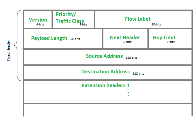
Version (4-bits): Indicates version of Internet Protocol which contains bit sequence 0110.
Traffic Class (8-bits): The Traffic Class field indicates class or priority of IPv6 packet which is similar to Service Field in IPv4 packet. It helps routers to handle the traffic based on the priority of the packet. If congestion occurs on the router then packets with the least priority will be discarded.
As of now, only 4-bits are being used (and the remaining bits are under research), in which 0 to 7 are assigned to Congestion controlled traffic and 8 to 15 are assigned to Uncontrolled traffic.
Priority assignment of Congestion controlled traffic :

Uncontrolled data traffic is mainly used for Audio/Video data. So we give higher priority to Uncontrolled data traffic.
The source node is allowed to set the priorities but on the way, routers can change it. Therefore, the destination should not expect the same priority which was set by the source node.
Flow Label (20-bits): Flow Label field is used by a source to label the packets belonging to the same flow in order to request special handling by intermediate IPv6 routers, such as non-default quality of service or real-time service. In order to distinguish the flow, an intermediate router can use the source address, a destination address, and flow label of the packets. Between a source and destination, multiple flows may exist because many processes might be running at the same time. Routers or Host that does not support the functionality of flow label field and for default router handling, flow label field is set to 0. While setting up the flow label, the source is also supposed to specify the lifetime of the flow.
Payload Length (16-bits): It is a 16-bit (unsigned integer) field, indicates the total size of the payload which tells routers about the amount of information a particular packet contains in its payload. The payload Length field includes extension headers(if any) and an upper-layer packet. In case the length of the payload is greater than 65,535 bytes (payload up to 65,535 bytes can be indicated with 16-bits), then the payload length field will be set to 0 and the jumbo payload option is used in the Hop-by-Hop options extension header.
Next Header (8-bits): Next Header indicates the type of extension header(if present) immediately following the IPv6 header. Whereas In some cases it indicates the protocols contained within upper-layer packets, such as TCP, UDP.
Hop Limit (8-bits): Hop Limit field is the same as TTL in IPv4 packets. It indicates the maximum number of intermediate nodes IPv6 packet is allowed to travel. Its value gets decremented by one, by each node that forwards the packet and the packet is discarded if the value decrements to 0. This is used to discard the packets that are stuck in an infinite loop because of some routing error.
Source Address (128-bits): Source Address is the 128-bit IPv6 address of the original source of the packet.
Destination Address (128-bits): The destination Address field indicates the IPv6 address of the final destination(in most cases). All the intermediate nodes can use this information in order to correctly route the packet.
Extension Headers: In order to rectify the limitations of the IPv4 Option Field, Extension Headers are introduced in IP version 6. The extension header mechanism is a very important part of the IPv6 architecture. The next Header field of IPv6 fixed header points to the first Extension Header and this first extension header points to the second extension header and so on.

IPv6 packet may contain zero, one or more extension headers but these should be present in their recommended order:

Rule: Hop-by-Hop options header(if present) should always be placed after the IPv6 base header.
Conventions :
- Any extension header can appear at most once except Destination Header because Destination Header is present two times in the above list itself.
- If Destination Header is present before Routing Header then it will be examined by all intermediate nodes specified in the routing header.
- If Destination Header is present just above the Upper layer then it will be examined only by the Destination node.
Given order in which all extension header should be chained in IPv6 packet and working of each extension header :

Introduction To Subnetting
When a bigger network is divided into smaller networks, to maintain security, then that is known as Subnetting. So, maintenance is easier for smaller networks. For example, if we consider a class A address, the possible number of hosts is 224 for each network, it is obvious that it is difficult to maintain such a huge number of hosts, but it would be quite easier to maintain if we divide the network into small parts.
Uses of Subnetting
- Subnetting helps in organizing the network in an efficient way which helps in expanding the technology for large firms and companies.
- Subnetting is used for specific staffing structures to reduce traffic and maintain order and efficiency.
- Subnetting divides domains of the broadcast so that traffic is routed efficiently, which helps in improving network performance.
- Subnetting is used in increasing network security.
The network can be divided into two parts: To divide a network into two parts, you need to choose one bit for each Subnet from the host ID part.

In the above diagram, there are two Subnets.
Note: It is a class C IP so, there are 24 bits in the network id part and 8 bits in the host id part.
Working of Subnetting
The working of subnets starts in such a way that firstly it divides the subnets into smaller subnets. For communicating between subnets, routers are used. Each subnet allows its linked devices to communicate with each other. Subnetting for a network should be done in such a way that it does not affect the network bits.
In class C the first 3 octets are network bits so it remains as it is.
- For Subnet-1: The first bit which is chosen from the host id part is zero and the range will be from (193.1.2.00000000 till you get all 1’s in the host ID part i.e, 193.1.2.01111111) except for the first bit which is chosen zero for subnet id part.
Thus, the range of subnet 1 is: 193.1.2.0 to 193.1.2.127
Subnet id of Subnet-1 is : 193.1.2.0 The direct Broadcast id of Subnet-1 is: 193.1.2.127 The total number of hosts possible is: 126 (Out of 128, 2 id's are used for Subnet id & Direct Broadcast id) The subnet mask of Subnet- 1 is: 255.255.255.128
- For Subnet-2: The first bit chosen from the host id part is one and the range will be from (193.1.2.100000000 till you get all 1’s in the host ID part i.e, 193.1.2.11111111).
Thus, the range of subnet-2 is: 193.1.2.128 to 193.1.2.255
Subnet id of Subnet-2 is : 193.1.2.128 The direct Broadcast id of Subnet-2 is: 193.1.2.255 The total number of hosts possible is: 126 (Out of 128, 2 id's are used for Subnet id & Direct Broadcast id) The subnet mask of Subnet- 2 is: 255.255.255.128 The best way to find out the subnet mask of a subnet is to set the fixed bit of host-id to 1 and the rest to 0.
Finally, after using the subnetting the total number of usable hosts is reduced from 254 to 252.
Note:
- To divide a network into four (22) parts you need to choose two bits from the host id part for each subnet i.e, (00, 01, 10, 11).
- To divide a network into eight (23) parts you need to choose three bits from the host id part for each subnet i.e, (000, 001, 010, 011, 100, 101, 110, 111) and so on.
- We can say that if the total number of subnets in a network increases the total number of usable hosts decreases.
Along with the advantage, there is a small disadvantage to subnetting that is, before subnetting to find the IP address first the network id is found then the host id followed by the process id, but after subnetting first network id is found then the subnet id then host id and finally process id by this the computation increases.
Example 1: An organization is assigned a class C network address of 201.35.2.0. It uses a netmask of 255.255.255.192 to divide this into sub-networks. Which of the following is/are valid host IP addresses?
- 201.35.2.129
- 201.35.2.191
- 201.35.2.255
- Both (A) and (C)
Solution:
Converting the last octet of the netmask into the binary form: 255.255.255.11000000 Converting the last octet of option 1 into the binary form: 201.35.2.10000001 Converting the last octet of option 2 into the binary form: 201.35.2.10111111 Converting the last octet of option 3 into the binary form: 201.35.2.11111111
From the above, we see that Options 2 and 3 are not valid host IP addresses (as they are broadcast addresses of a subnetwork), and OPTION 1 is not a broadcast address and it can be assigned to a host IP.
Advantages of Subnetting
The advantages of Subnetting are mentioned below:
- It provides security to one network from another network. eg) In an Organisation, the code of the Developer department must not be accessed by another department.
- It may be possible that a particular subnet might need higher network priority than others. For example, a Sales department needs to host webcasts or video conferences.
- In the case of Small networks, maintenance is easy.
Disadvantages of Subnetting
The disadvantages of Subnetting are mentioned below:
- In the case of a single network, only three steps are required to reach a Process i.e Source Host to Destination Network, Destination Network to Destination Host, and then Destination Host to Process.
- In the case of a Single Network only two IP addresses are wasted to represent Network Id and Broadcast address but in the case of Subnetting two IP addresses are wasted for each Subnet.
- The cost of the overall Network also increases. Subnetting requires internal routers, Switches, Hubs, Bridges, etc. which are very costly.
Network Layer Protocols
TCP/IP supports the following protocols:
ARP
- ARP stands for Address Resolution Protocol.
- It is used to associate an IP address with the MAC address.
- Each device on the network is recognized by the MAC address imprinted on the NIC. Therefore, we can say that devices need the MAC address for communication on a local area network. MAC address can be changed easily. For example, if the NIC on a particular machine fails, the MAC address changes but IP address does not change. ARP is used to find the MAC address of the node when an internet address is known.
Note: MAC address: The MAC address is used to identify the actual device.
IP address: It is an address used to locate a device on the network.
How ARP works
If the host wants to know the physical address of another host on its network, then it sends an ARP query packet that includes the IP address and broadcast it over the network. Every host on the network receives and processes the ARP packet, but only the intended recipient recognizes the IP address and sends back the physical address. The host holding the datagram adds the physical address to the cache memory and to the datagram header, then sends back to the sender.
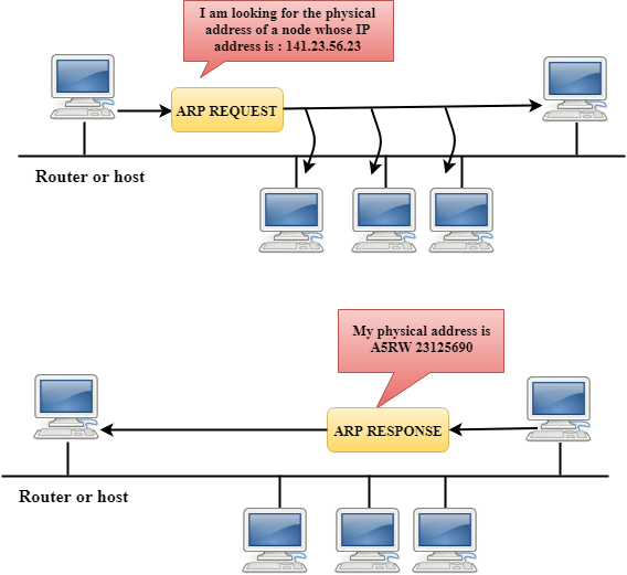
Steps taken by ARP protocol
If a device wants to communicate with another device, the following steps are taken by the device:
- The device will first look at its internet list, called the ARP cache to check whether an IP address contains a matching MAC address or not. It will check the ARP cache in command prompt by using a command arp-a.

- If ARP cache is empty, then device broadcast the message to the entire network asking each device for a matching MAC address.
- The device that has the matching IP address will then respond back to the sender with its MAC address
- Once the MAC address is received by the device, then the communication can take place between two devices.
- If the device receives the MAC address, then the MAC address gets stored in the ARP cache. We can check the ARP cache in command prompt by using a command arp -a.
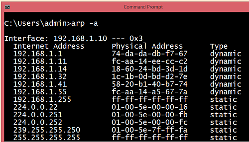
Note: ARP cache is used to make a network more efficient.
In the above screenshot, we observe the association of IP address to the MAC address.
There are two types of ARP entries:
- Dynamic entry: It is an entry which is created automatically when the sender broadcast its message to the entire network. Dynamic entries are not permanent, and they are removed periodically.
- Static entry: It is an entry where someone manually enters the IP to MAC address association by using the ARP command utility.
RARP
- RARP stands for Reverse Address Resolution Protocol.
- If the host wants to know its IP address, then it broadcast the RARP query packet that contains its physical address to the entire network. A RARP server on the network recognizes the RARP packet and responds back with the host IP address.
- The protocol which is used to obtain the IP address from a server is known as Reverse Address Resolution Protocol.
- The message format of the RARP protocol is similar to the ARP protocol.
- Like ARP frame, RARP frame is sent from one machine to another encapsulated in the data portion of a frame.

ICMP
- ICMP stands for Internet Control Message Protocol.
- The ICMP is a network layer protocol used by hosts and routers to send the notifications of IP datagram problems back to the sender.
- ICMP uses echo test/reply to check whether the destination is reachable and responding.
- ICMP handles both control and error messages, but its main function is to report the error but not to correct them.
- An IP datagram contains the addresses of both source and destination, but it does not know the address of the previous router through which it has been passed. Due to this reason, ICMP can only send the messages to the source, but not to the immediate routers.
- ICMP protocol communicates the error messages to the sender. ICMP messages cause the errors to be returned back to the user processes.
- ICMP messages are transmitted within IP datagram.
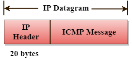
The Format of an ICMP message

- The first field specifies the type of the message.
- The second field specifies the reason for a particular message type.
- The checksum field covers the entire ICMP message.
Error Reporting
ICMP protocol reports the error messages to the sender.
Five types of errors are handled by the ICMP protocol:
- Destination unreachable
- Source Quench
- Time Exceeded
- Parameter problems
- Redirection

- Destination unreachable: The message of "Destination Unreachable" is sent from receiver to the sender when destination cannot be reached, or packet is discarded when the destination is not reachable.
- Source Quench: The purpose of the source quench message is congestion control. The message sent from the congested router to the source host to reduce the transmission rate. ICMP will take the IP of the discarded packet and then add the source quench message to the IP datagram to inform the source host to reduce its transmission rate. The source host will reduce the transmission rate so that the router will be free from congestion.
- Time Exceeded: Time Exceeded is also known as "Time-To-Live". It is a parameter that defines how long a packet should live before it would be discarded.
There are two ways when Time Exceeded message can be generated:
Sometimes packet discarded due to some bad routing implementation, and this causes the looping issue and network congestion. Due to the looping issue, the value of TTL keeps on decrementing, and when it reaches zero, the router discards the datagram. However, when the datagram is discarded by the router, the time exceeded message will be sent by the router to the source host.
When destination host does not receive all the fragments in a certain time limit, then the received fragments are also discarded, and the destination host sends time Exceeded message to the source host.
- Parameter problems: When a router or host discovers any missing value in the IP datagram, the router discards the datagram, and the "parameter problem" message is sent back to the source host.
- Redirection: Redirection message is generated when host consists of a small routing table. When the host consists of a limited number of entries due to which it sends the datagram to a wrong router. The router that receives a datagram will forward a datagram to a correct router and also sends the "Redirection message" to the host to update its routing table.
IGMP
- IGMP stands for Internet Group Message Protocol.
- The IP protocol supports two types of communication:
- Unicasting: It is a communication between one sender and one receiver. Therefore, we can say that it is one-to-one communication.
- Multicasting: Sometimes the sender wants to send the same message to a large number of receivers simultaneously. This process is known as multicasting which has one-to-many communication.
- The IGMP protocol is used by the hosts and router to support multicasting.
- The IGMP protocol is used by the hosts and router to identify the hosts in a LAN that are the members of a group.
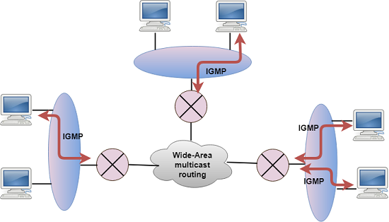
- IGMP is a part of the IP layer, and IGMP has a fixed-size message.
- The IGMP message is encapsulated within an IP datagram.
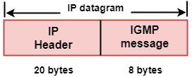
The Format of IGMP message

Where,
Type: It determines the type of IGMP message. There are three types of IGMP message: Membership Query, Membership Report and Leave Report.
Maximum Response Time: This field is used only by the Membership Query message. It determines the maximum time the host can send the Membership Report message in response to the Membership Query message.
Checksum: It determines the entire payload of the IP datagram in which IGMP message is encapsulated.
Group Address: The behavior of this field depends on the type of the message sent.
- For Membership Query, the group address is set to zero for General Query and set to multicast group address for a specific query.
- For Membership Report, the group address is set to the multicast group address.
- For Leave Group, it is set to the multicast group address.
DHCP
Dynamic Host Configuration Protocol (DHCP) is a network management protocol used to dynamically assign an IP address to nay device, or node, on a network so they can communicate using IP (Internet Protocol). DHCP automates and centrally manages these configurations. There is no need to manually assign IP addresses to new devices. Therefore, there is no requirement for any user configuration to connect to a DHCP based network.
DHCP can be implemented on local networks as well as large enterprise networks. DHCP is the default protocol used by the most routers and networking equipment. DHCP is also called RFC (Request for comments) 2131.
DHCP does the following:
- DHCP manages the provision of all the nodes or devices added or dropped from the network.
- DHCP maintains the unique IP address of the host using a DHCP server.
- It sends a request to the DHCP server whenever a client/node/device, which is configured to work with DHCP, connects to a network. The server acknowledges by providing an IP address to the client/node/device.
DHCP is also used to configure the proper subnet mask, default gateway and DNS server information on the node or device.
There are many versions of DCHP are available for use in IPV4 (Internet Protocol Version 4) and IPV6 (Internet Protocol Version 6)
Unicast Routing Algorithms: RIP, OSPF, BGP
Unicast routing algorithms are used to determine the optimal path for transmitting data from a source to a destination in a network. Here's an overview of three prominent unicast routing protocols: RIP (Routing Information Protocol), OSPF (Open Shortest Path First), and BGP (Border Gateway Protocol).
-
RIP (Routing Information Protocol):
- Type: Distance Vector Protocol.
- Algorithm: Bellman-Ford algorithm.
- Metric: Hop count (number of routers or hops to reach the destination).
- Updates: Periodic updates are sent (every 30 seconds) to share routing information with neighboring routers.
- Convergence: May experience slow convergence due to the periodic update mechanism.
- Use Case: Suitable for small to medium-sized networks; less scalable for large networks or those with complex topologies.
- Version: RIP version 1 and RIP version 2 (RIPv2) are commonly used.
-
OSPF (Open Shortest Path First):
-
Type: Link State Protocol.
- Algorithm: Dijkstra's Shortest Path First (SPF) algorithm.
- Metric: Cost based on bandwidth.
- Updates: Routers exchange link-state information only when there is a change in the network topology.
- Convergence: Faster convergence compared to RIP due to incremental updates.
- Use Case: Well-suited for large and complex networks, especially those with multiple paths and high bandwidth.
- Areas: Divides the network into areas to enhance scalability.
-
BGP (Border Gateway Protocol):
-
Type: Path Vector Protocol.
- Algorithm: Policy-based decision-making considering multiple factors (path attributes).
- Metric: Path attributes, including AS path, next-hop, and various policies set by network administrators.
- Updates: BGP routers exchange routing information only when there is a change in the network or policy.
- Convergence: Slower convergence compared to interior gateway protocols due to the policy-based decision-making process.
- Use Case: Primarily used for inter-domain routing on the Internet. Connects different autonomous systems (AS).
- Features: Provides rich policy control and is highly scalable, making it suitable for large-scale networks.
References
https://www.geeksforgeeks.org/classification-of-routing-algorithms/ https://www.geeksforgeeks.org/optimality-principle-in-network-topology/ https://www.tutorialspoint.com/what-is-the-shortest-path-routing-in-computer-network https://www.tutorialspoint.com/flooding-in-computer-network https://www.geeksforgeeks.org/distance-vector-routing-dvr-protocol/ https://www.javatpoint.com/link-state-routing-algorithm https://www.geeksforgeeks.org/difference-between-hierarchical-and-flat-routing-protocol/ https://www.javatpoint.com/ip https://www.geeksforgeeks.org/what-is-ipv4/ https://www.tutorialspoint.com/ipv4-exhaustion-in-computer-network https://www.geeksforgeeks.org/internet-protocol-version-6-ipv6-header/ https://www.geeksforgeeks.org/introduction-to-subnetting/ https://www.javatpoint.com/network-layer-protocols https://www.javatpoint.com/dynamic-host-configuration-protocol